| Feature Dimensions |
SDMH-UU (Steel-reinforced rectangular flange / double-beveled type) |
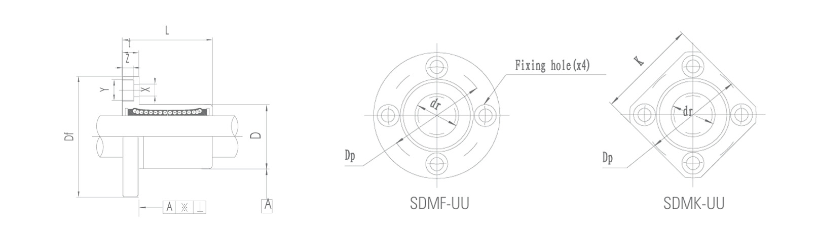
SDMF-UU (Steel Round Flange Type) |
SDMK-UU (Steel Width-Retaining Flange Type) |
Core Value Proposition |
| Core Positioning |
High rigidity, high torque resistance, and the ultimate in compact design. |
A robust, economical and compact universal solution. |
The heavy-duty specialist offering ultimate rigidity and exceptional torque resistance. |
A perfect balance between the compactness of the F-type and the robustness of the K-type. |
| Flange Design |
Rectangular (double-beveled) flange. By removing the unnecessary sections of a circular flange, two parallel, wide mounting surfaces are created, with mounting holes positioned on both sides. |
Full-circle flange with evenly spaced mounting holes. |
Wide square or rectangular flanges, suitable for four-corner or multi-point mounting. |
The H-type design provides the maximum effective moment-resisting arm using the minimum amount of material. |
| Space Efficiency |
Extremely high. Whilst offering excellent torque resistance, its maximum profile dimensions (particularly in the diagonal direction) are significantly smaller than those of the K-type with equivalent load-bearing capacity, making it easier to integrate into compact structures. |
High. The circular profile may occupy unnecessary space in certain layouts. |
Low. Requires a large mounting surface to accommodate the wide flanges. |
The H-type is the high-rigidity flange solution offering the highest space utilisation. |
| Resistance to Overturning Moments |
Strong. The wide faces created by the double-beveled design provide a significantly greater moment-resisting lever arm than round flanges, particularly when resisting torques acting perpendicular to the axis of the wide faces. |
Medium. |
Extremely strong. Provides maximum torque resistance in all directions. |
It provides ample rigidity for most applications involving moderate eccentric moments, without wasting space. |
| Ease of Installation |
High. The two parallel mounting surfaces are easy to machine and align, and require less mounting plate material than the K-type. |
High. |
High, but requires a larger mounting area. |
The layout advantages of the H-type are particularly evident in narrow, elongated spaces or modular designs. |
| Advantages of Steel Construction |
Fully equipped. The steel retainer ensures high-speed, high-temperature and long-life operational performance. |
Fully equipped. |
Fully equipped. |
Shares the same top-tier core dynamic performance foundation. |
 English
 Português
 русский
 Español
 The LMHC-L-UU series linear bearing is a high-performance linear bearing that combine...
 The LMFC/LMKC series linear bearing is a special type of linear bearing with a flange...
 The LMHP-L-UU series linear bearing is a pinnacle of design, combining four key featu...
 The LMFP-L/LMKP-L series linear bearings are linear bearings that combine three core ...
 The LMHP-UU series linear bearing is a high-end linear bearing that combines three ke...


