Follow us
Products · Products · Products · Products · Products · Products · Products · Products · Products · Products · Products · Products · Products · Products · Products · Products ·

LMFC-L-UU/LMKC-L-UU Center-Mount Long Type Flanged Linear Bearing

Home · Products · Linear Bearing · LMFC-L-UU/LMKC-L-UU Center-Mount Long Type Flanged Linear Bearing
LMFC-L-UU/LMKC-L-UU Center-Mount Long Type Flanged Linear Bearing

LMFC-L-UU/LMKC-L-UU Center-Mount Long Type Flanged Linear Bearing

The LMFC/LMKC series linear bearing is a special type of linear bearing with a flange mounting surface located in the middle of the bearing body. Unlike standard designs where the flange is located at one end, this "center-mounted flange" structure provides symmetrical support length on both sides, achieving excellent torque balance and force distribution after installation. It is designed for special applications requiring extremely high anti-tilting stability, symmetrical force distribution, or applications requiring straddle mounting.

Technology

Core Sub-series Comparison and Selection Guide

Product Characteristics 
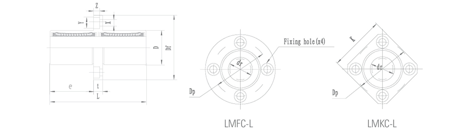
LMFC-L-UU (Centre-mounted circular flange, extended type) LMKC-L-UU (Centre-mounted flange, extended type) Key Selection Criteria
Core Positioning A circular flange design featuring symmetrical support, high resistance to overturning, and self-balancing of torque. A flange solution offering symmetrical support, ultimate anti-overturning performance and stability for extra-long spans. When the load’s centre of gravity must be precisely located at the centre of the support, or when the installation structure requires symmetrical support on both sides, the centre-mounted flange Type C must be selected.
Key Structural Features The flange is positioned at the midpoint of the bearing housing. Once installed, the bearing has equal overhang lengths on both sides of the flange. The flange itself is circular. The flange is also positioned at the centre of the main body and is square or rectangular in shape. ‘Centre-mounted’ is the key characteristic, determining its unique mechanical behaviour and distinguishing it fundamentally from ‘single-ended’ flanges.
Key Advantages 1. Automatic torque balancing: When a load is applied to the centre of the bearing, the forces on the two support points are perfectly equal, fundamentally eliminating the additional bending moment caused by a single-sided cantilever.
2. Excellent resistance to overturning: The symmetrical structure enables it to resist overturning moments from any direction far better than single-flange bearings of the same size.
3. Suitable for ‘straddle’ mounting: Can be stably mounted on U-channels, on both sides of a frame, or atop a beam.
1. Ultimate rigidity with symmetrical support: Combining the balance of a centre-mounted design with the torque-resisting capability of a flange, it provides unrivalled overall stability.
2. Support for extremely large spans: Suitable as the core of two-point or multi-point symmetrical support systems for long slides or large-scale worktables.
3. Clear installation reference: The centre-mounted flange itself serves as a natural central positioning reference.
Type FC resolves the issue of symmetrical loading, whilst Type KC pursues maximum rigidity on the basis of symmetry.
Mechanical Properties Highly symmetrical. Demonstrates outstanding performance in resisting overturning moments caused by central loads, with symmetrical and predictable system deformation. Extremely high and comprehensive. Under symmetrical support conditions, it provides top-tier bending, torsional and overturning rigidity in all directions. The centre-mounted design concentrates the rigidity advantage on resisting “overturning” rather than “cantilever bending”.
Installation and Applications Commonly used in lifting mechanisms requiring centralised fixation, clamping devices subject to symmetrical forces, and central adjustment platforms for optical components. Used for symmetrical support points on large gantry moving components, central bearing housings for heavy-duty rotary tables, and central slides on high-precision measuring machines. Application scenarios are heavily dependent on the geometric and mechanical requirement of “central symmetry”.

Technical Focus: The Unique Mechanical Value of the Center-Mounted Flange
1. Solving the fundamental problem: When standard single-ended flange bearings bear a load, the flange mounting point is subjected to asymmetrical torque, which can easily lead to local deformation of the mounting plate. The center-mounted flange symmetrically distributes the load to both sides, so the mounting point mainly bears shear force, resulting in a better stress state and minimal deformation of the mounting plate.
2. Simplifying design calculations: For designs requiring precise centering, using a center-mounted flange bearing eliminates the need for complex off-center load calculations and reinforcement designs, as the load is automatically centered and distributed.

Applications
The LMFC/LMKC-L-UU series center-mount long type flanged linear bearing is the ideal choice for the following specialized fields with stringent requirements for "centering" and "symmetrical stability":
Precision optical and laser systems: Adjustment frames for laser mirrors and optical lenses, requiring the point of application of the driving force to pass strictly through the optical center.
High-end testing equipment: Spindle support for roundness measuring instruments and dynamic balancing machines, requiring the center of rotation to coincide with the center of support.
Special fixtures and molds: Guiding of hydraulic or pneumatic central clamping devices, ensuring that the clamping force does not produce an offset bending moment.
Heavy-duty precision translation stages: Sample transfer mechanisms in large vacuum chambers, requiring symmetrical two-point support within a limited space.

The LMFC/LMKC-L-UU series center-mount long type flanged linear bearing is not a general-purpose product, but a "specialized weapon" designed to solve specific, high-level engineering problems.
It does not aim to perform excellently in all scenarios, but in the niche requirement of "symmetrical support" and "torque balance," it provides an irreplaceable standard solution. Choosing this series means your design has encountered a classic mechanical positioning problem, and you've chosen to solve it with elegant, reliable, and standardized components.
It represents a leap in engineering thinking, from simply "functional" to "ingeniously effective," and is the go-to "professional tool" in the toolbox of experienced mechanical engineers when faced with complex constraints.

Parameters

NomInal shaft
diameter
(mm)
Part No. Major dimenslons and tolerance
Steel dr D L Flange
LMF(K)C...LUU mm Tolerance(μm) mm Tolerance(μm) mm Tolerance(μm) e
mm
Df
mm
K
mm
6 LMFC 6L-UU 6 0-10 12 0-13 35 ±300 15 28 22
LMKC 6L-UU
8 LMFC 8L-UU 8 0-10 15 0-13 45 ±300 20 32 25
LMKC 8L-UU
10 LMFC 10L-UU 10 0-10 19 0-16 55 ±300 24.5 40 30
LMKC 10L-UU
12 LMFC 12L-UU 12 0-10 21 0-16 57 ±300 25.5 42 32
LMKC 12L-UU
13 LMFC 13L-UU 13 0-10 23 0-16 61 ±300 27.5 43 34
LMKC 13L-UU
16 LMFC 16L-UU 16 0-10 28 0-16 70 ±300 32 48 37
LMKC 16L-UU
20 LMFC 20L-UU 20 0-12 32 0-19 80 ±300 36 54 42
LMKC 20L-UU
25 LMFC 25L-UU 25 0-12 40 0-19 112 ±300 52 62 50
LMKC 25L-UU
30 LMFC 30L-UU 30 0-12 45 0-19 123 ±300 56.5 74 58
LMKC 30L-UU
35 LMFC 35L-UU 35 0-15 52 0-22 135 ±300 62.5 82 64
LMKC 35L-UU
40 LMFC 40L-UU 40 0-15 60 0-22 151 ±300 69 96 75
LMKC 40L-UU
50 LMFC 50L-UU 50 0-15 80 0-22 192 ±300 89.5 116 92
LMKC 50L-UU
60 LMFC 60L-UU 60 0-20 90 0-25 209 ±300 95.5 134 106
LMKC 60L-UU

Part No. Major dimenslons and tolerance Eccentricity(μm) Squareness(μm) Basic load rating Weight
g
NomInal shaft
diameter
(mm)
Steel Flange dynamic
(C N)
static
(Co N)
LMF(K)C...LUU t
mm
Dp
mm
X
mm
Y
mm
Z
mm
LMFC 6L-UU 5 20 3.5 6.5 3.1 15 15 323 529 31 6
LMKC 6L-UU 25
LMFC 8L-UU 5 24 3.5 6.5 3.1 15 15 431 784 51 8
LMKC 8L-UU 43
LMFC 10L-UU 6 29 4.5 8 4.1 15 15 588 1100 98 10
LMKC 10L-UU 78
LMFC 12L-UU 6 32 4.5 8 4.1 15 15 813 1570 110 12
LMKC 12L-UU 90
LMFC 13L-UU 6 33 4.5 8 4.1 15 15 813 1570 130 13
LMKC 13L-UU 108
LMFC 16L-UU 6 38 4.5 8 4.1 15 15 1230 2350 190 16
LMKC 16L-UU 165
LMFC 20L-UU 8 43 5.5 9.5 5.1 20 20 1400 2740 260 20
LMKC 20L-UU 225
LMFC 25L-UU 8 51 5.5 9.5 5.1 20 20 1560 3140 540 25
LMKC 25L-UU 500
LMFC 30L-UU 10 60 6.6 11 6.1 20 20 2490 5490 680 30
LMKC 30L-UU 590
LMFC 35L-UU 10 67 6.6 11 6.1 25 25 2650 6270 1020 35
LMKC 35L-UU 930
LMFC 40L-UU 13 78 9 14 8.1 25 25 3430 8040 1570 40
LMKC 40L-UU 1380
LMFC 50L-UU 13 98 9 14 8.1 25 25 6080 15900 3600 50
LMKC 50L-UU 3400
LMFC 60L-UU 18 112 11 17.5 11.1 30 30 7550 20000 4500 60
LMKC 60L-UU 4060

Drawings