Technical Parameter Details
Structural Specifications Analysis
Model Explanation: LMHC-L-UU
LM: Linear Bearing Series
H: Double-edged structure (special anti-rotation design)
C: Central/Center Flange position
L: Extended type (core advantage multiplier)
UU: Double-ended contact seal
Performance Triple Advantage
1. Extended Type (L) Core Value
Increased Rigidity: 40-60% higher rigidity than standard type, significantly reduced deformation
Extended Lifespan: Better load distribution, theoretical lifespan increased by more than 50%
Smooth Operation: Extended guidance, strong resistance to eccentric loads, no jamming or vibration
2. Double-edged (H) Space Advantage
Compact Arrangement: Supports minimum bearing center distance design
Reliable Anti-rotation: Mechanical edge anti-rotation, no risk of loosening
Installation Datum: The edge plane can be used as a machining and assembly datum surface
3. Centralized (C) Mechanical Advantage
Automatic Alignment: Load is automatically and evenly distributed to both sides
Zero Additional Bending Moment: Eliminates eccentric load deformation of the mounting plate from the source
Anti-overturning: Increased resistance to overturning moment by 2-3 times
Applications
High-density multi-axis synchronous systems
Precision 3D printing equipment: Multiple print heads independently driven, requiring compact arrangement and high-precision synchronization
Electronic SMT production lines: High-density, high-precision support for multiple placement heads, dispensing heads, and inspection heads
Micro-robot arm arrays: Collaboration Space Optimization Solutions for Robot Joints
Medical and Laboratory Equipment
Surgical Robot Guidance Module: Compact structure required for sterile environments, absolutely smooth operation
Gene Sequencer Mobile Platform: Requires long-term stable operation, extremely high resistance to micro-vibrations
Laboratory Automation Workstation: Multi-station compact layout, independent and precise movement of each axis
Special Industrial Equipment
Compact CNC Engraving Machine: Limited working space, requires high-rigidity multi-axis support
Micro Injection Molding Machine Pick-and-Place Robot: Stable guidance in compact spaces under high-temperature environments
Precision Inspection Instrument Multi-Probe System: Multiple sensors require dense arrangement and independent precise positioning
Complete Selection and Installation Guide
Selection Decision Matrix
Key Installation Steps
1. Installation Surface Pre-treatment
Flatness requirement: ≤0.02mm/100mm
Double-edged groove machining: Width tolerance H7, depth control ±0.1mm
Surface treatment: Anodizing or chrome plating recommended for corrosion resistance
2. Alignment and Assembly Process
Use the double-edged plane for initial positioning
Pre-tighten all bolts to 30% torque
Measure the height difference of the two cantilevered ends using a dial indicator, adjust to ≤0.01mm
Tighten to full torque in a cross-pattern sequence
3. Running Verification Points
Manually push under no load, feel for uniform damping throughout the entire range
Load 50% of the rated load, check for smooth operation
Monitor temperature rise during long-term operation, should be ≤40℃ above ambient temperature
The LMHC-L-UU center-mount double-cut linear bearing is not a general-purpose part, but an elegant solution to specific engineering problems.
Its existence answers three core questions:
1. When space is at a premium, how to avoid sacrificing performance?
→ Answer: Double-edged design, minimum radial footprint
2. When absolute anti-rotation reliability is required, how to avoid complex structures?
→ Answer: Mechanical edge anti-rotation, simple and reliable
3. When long life and high rigidity are required, how to achieve this in a compact space? → Answer: Extended design, enhanced rigidity and lifespan.
Profile of engineers who choose LMHC-L-UU:
You refuse to compromise on standards just because of limited space.
You believe that excellent design can lead to innovation even within constraints.
You understand that "the right specialized component" is more valuable than a "generic reinforced component."
You strive to embody engineering intelligence in every detail.
Value Proposition:
In the same installation space, the LMHC-L-UU linear bearing offers:
Higher rigidity than standard types
Better anti-rotation than round flange types
Superior space utilization compared to any other solution
Simpler system integration from the design stage
This is more than just a bearing choice; it's an engineering declaration of pursuing unlimited possibilities in limited space. For applications where every inch of space is precious and every movement is critical, the LMHC-L-UU is the key, precise, and reliable technological component.
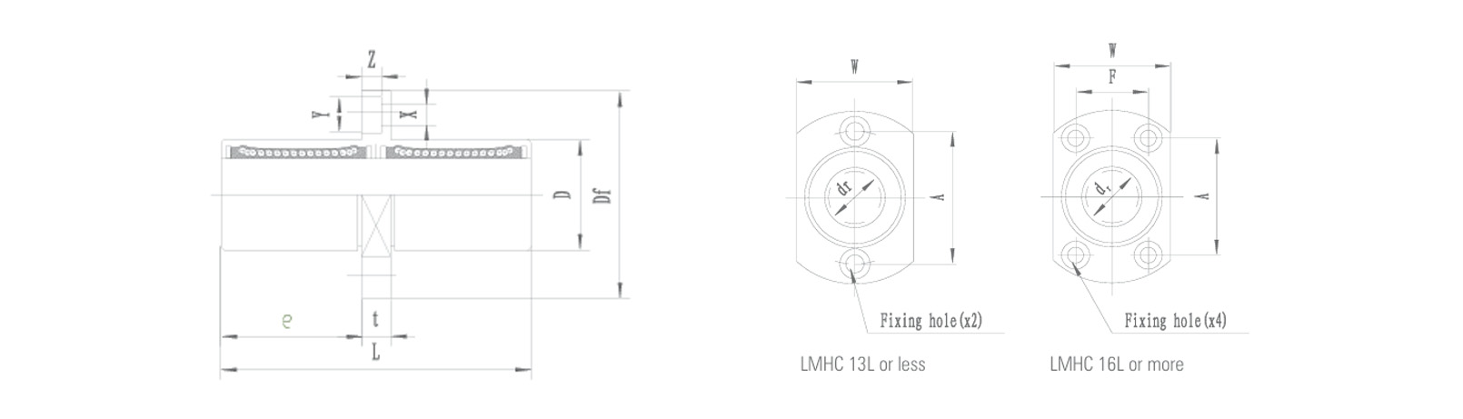
Parameters
NomInal shaft
diameter
(mm) |
Part No. |
Major dimenslons and tolerance |
| Steel |
dr |
D |
L |
Flange |
| LMHC...LUU |
mm |
Tolerance(μm) |
mm |
Tolerance(μm) |
mm |
Tolerance(μm) |
e
mm |
Df
mm |
W
mm |
t
mm |
| 6 |
LMHC 6L-UU |
6 |
0-10 |
12 |
0-13 |
35 |
±300 |
15 |
28 |
18 |
5 |
| 8 |
LMHC 8L-UU |
8 |
0-10 |
15 |
0-13 |
45 |
±300 |
20 |
32 |
21 |
5 |
| 10 |
LMHC 10L-UU |
10 |
0-10 |
19 |
0-16 |
55 |
±300 |
24.5 |
40 |
25 |
6 |
| 12 |
LMHC 12L-UU |
12 |
0-10 |
21 |
0-16 |
57 |
±300 |
25.5 |
42 |
27 |
6 |
| 13 |
LMHC 13L-UU |
13 |
0-10 |
23 |
0-16 |
61 |
±300 |
27.5 |
43 |
29 |
6 |
| 16 |
LMHC 16L-UU |
16 |
0-10 |
28 |
0-16 |
70 |
±300 |
32 |
48 |
34 |
6 |
| 20 |
LMHC 20L-UU |
20 |
0-12 |
32 |
0-19 |
80 |
±300 |
36 |
54 |
38 |
8 |
| 25 |
LMHC 25L-UU |
25 |
0-12 |
40 |
0-19 |
112 |
±300 |
52 |
62 |
46 |
8 |
| 30 |
LMHC 30L-UU |
30 |
0-12 |
45 |
0-19 |
123 |
±300 |
56.5 |
74 |
51 |
10 |
| Part No. |
Major dimenslons and tolerance |
Eccentricity(μm) |
Squareness(μm) |
Basic load rating |
Weight
g |
NomInal shaft
diameter
(mm) |
| Steel |
Flange |
dynamic
(C N) |
static
(Co N) |
| LMHC...LUU |
A
mm |
Dp
mm |
X
mm |
Y
mm |
Z
mm |
| LMHC 6L-UU |
20 |
- |
3.5 |
6.5 |
3.1 |
15 |
15 |
323 |
529 |
28 |
6 |
| LMHC 8L-UU |
24 |
- |
3.5 |
6.5 |
3.1 |
15 |
15 |
431 |
784 |
47 |
8 |
| LMHC 10L-UU |
29 |
- |
4.5 |
8 |
4.1 |
15 |
15 |
588 |
1100 |
90 |
10 |
| LMHC 12L-UU |
32 |
- |
4.5 |
8 |
4.1 |
15 |
15 |
813 |
1570 |
102 |
12 |
| LMHC 13L-UU |
33 |
- |
4.5 |
8 |
4.1 |
15 |
15 |
813 |
1570 |
123 |
13 |
| LMHC 16L-UU |
31 |
22 |
4.5 |
8 |
4.1 |
15 |
15 |
1230 |
2350 |
182 |
16 |
| LMHC 20L-UU |
36 |
24 |
5.5 |
9.5 |
5.1 |
20 |
20 |
1400 |
2740 |
247 |
20 |
| LMHC 25L-UU |
40 |
32 |
5.5 |
9.5 |
5.1 |
20 |
20 |
1560 |
3140 |
525 |
25 |
| LMHC 30L-UU |
49 |
35 |
6.6 |
11 |
6.1 |
20 |
20 |
2490 |
5490 |
645 |
30 |
Drawings
 English
 Português
 русский
 Español
 The LMHC-L-UU series linear bearing is a high-performance linear bearing that combine...
 The LMFC/LMKC series linear bearing is a special type of linear bearing with a flange...
 The LMHP-L-UU series linear bearing is a pinnacle of design, combining four key featu...
 The LMFP-L/LMKP-L series linear bearings are linear bearings that combine three core ...
 The LMHP-UU series linear bearing is a high-end linear bearing that combines three ke...


