Main Technical Parameters and Design
1. Structure and Working Principle:
End Hubs: Usually made of aluminum alloy, lightweight, with 90-degree vertical rectangular grooves.
Intermediate Slider: The core component, typically made of engineering plastic (such as POM) or copper alloy. Plastic sliders are lubrication-free, low-noise, and low-inertia; metal sliders have a longer lifespan and are more temperature-resistant, but require lubrication.
Working Principle: The protrusions on both sides of the slider are embedded in the grooves of the two end hubs. When there is radial misalignment between the two shafts, the slider automatically self-aligns by sliding within the two pairs of vertical grooves, thereby transmitting torque.
2. Key Performance and Limitations:
Zero Backlash Transmission: Rigid contact, no elastic elements, ensuring high synchronicity.
Speed Limitation: Due to sliding friction, its maximum allowable speed is usually low, and it is not suitable for high-speed long-term operation, otherwise it will fail due to increased heat generation and wear.
Not Suitable for Angular Misalignment: If angular misalignment exists, point contact or line contact will occur between the slider and the grooves, leading to abnormal wear and jamming.
3. Selection Considerations:
First, confirm that the radial misalignment is within the product's allowable range.
Clearly define the operating speed; it must be within the safe zone of the "speed-misalignment" curve in the product catalog.
Consider the installation space thickness, which is one of its major advantages. Applications
The SZHK series is irreplaceable in areas where spatial constraints and radial misalignment are significant challenges:
Encoders and servo feedback: Connecting servo motor shafts to encoders, compensating for misalignment during installation.
Miniature precision equipment: Micro-drive connections for small instruments, optical instruments, and semiconductor grippers.
Printing and textile machinery: Synchronous transmission between multiple parallel roller shafts with inherent center distance errors.
Any transmission application with extreme limitations on axial installation space.
The SZHK Series Oldham Type Cross-shaped Coupling is a "space magician" and "eccentricity nemesis" in mechanical design. Choosing the SZHK series means you have found an excellent solution in both spatial and radial misalignment dimensions. Although it requires regular maintenance and replacement of the sliders, its performance advantages in its specialized applications are unmatched by other types of couplings. It is a classic and effective tool in the toolbox of precision equipment engineers when dealing with compact layouts and installation errors.
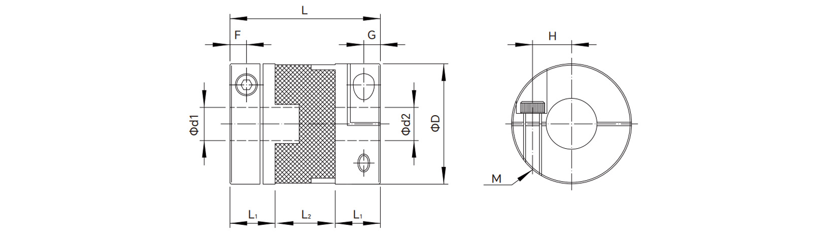
Parameters
| Model No. |
d1/d2 pore size |
D
(mm) |
L
(mm) |
L1
(mm) |
L2
(mm) |
F
(mm) |
H
(mm) |
Screw size
M |
Tightening torque
(N.m) |
Rated torque
(N.m) |
Maximum torque
(N.m) |
Maximum speed
(RPM) |
Moment of inertia
(kg·m²) |
Static torsional stiffness
(N.m/
rad) |
Permissible eccentricity
(mm) |
Permissible deviation
(° ) |
Axial runout
(mm) |
Min
(mm) |
Max
(mm) |
| SZHK-D20*25 |
4 |
10 |
20 |
25 |
9.5 |
6 |
3 |
7 |
M3 |
1.5 |
1.5 |
3 |
7000 |
1.5*10-7 |
60 |
1.2 |
3 |
±0.2 |
| SZHK-D20*33 |
4 |
10 |
20 |
33 |
10 |
12 |
3 |
7 |
M3 |
1.5 |
1.5 |
3 |
7000 |
1.5*10-7 |
60 |
1.2 |
3 |
±0.2 |
| SZHK-D25*28 |
5 |
12 |
25 |
28 |
10.5 |
7 |
3 |
9.5 |
M3 |
1.5 |
2 |
4 |
6100 |
3.2*10-6 |
130 |
1.6 |
3 |
±0.2 |
| SZHK-D25*39 |
5 |
12 |
25 |
39 |
11 |
17 |
3 |
9.5 |
M3 |
1.5 |
2 |
4 |
6100 |
3.2*10-6 |
130 |
1.6 |
3 |
±0.2 |
| SZHK-D32*45 |
6 |
15 |
32 |
45 |
12.5 |
20 |
5 |
11 |
M4 |
3.5 |
5 |
9 |
4800 |
2.6*10-5 |
275 |
2 |
3 |
±0.2 |
| SZHK-D34*35 |
6 |
17 |
34 |
35 |
13 |
9 |
5 |
11 |
M4 |
3.5 |
5 |
9 |
4800 |
2.8*10-5 |
275 |
2 |
3 |
±0.2 |
| SZHK-D40*50 |
8 |
20 |
40 |
50 |
15.5 |
19 |
5.5 |
14.5 |
M5 |
8 |
10 |
20 |
3600 |
4.2*10-5 |
520 |
2.7 |
3 |
±0.2 |
| SZHK-D44*46 |
8 |
22 |
44 |
46 |
15.5 |
15 |
5.5 |
16.5 |
M5 |
8 |
13 |
26 |
3600 |
4.5*10-5 |
520 |
3 |
3 |
±0.2 |
| SZHK-D50*58 |
10 |
26 |
50 |
58 |
19.5 |
19 |
6.5 |
18.5 |
M6 |
13 |
19 |
37 |
3000 |
1.1*10-4 |
800 |
3 |
3 |
±0.2 |
| SZHK-D55*58 |
10 |
28 |
55 |
58 |
20.5 |
17 |
6.5 |
21 |
M6 |
13 |
25 |
50 |
3000 |
1.3*10-4 |
1200 |
3.2 |
3 |
±0.2 |
| SZHK-D63*71 |
14 |
35 |
63 |
71 |
24.5 |
22 |
8 |
23.5 |
M8 |
28 |
33 |
65 |
2600 |
3.5*10-4 |
1200 |
3.5 |
3 |
±0.2 |
| SZHK-D70*77 |
16 |
37 |
70 |
77 |
26.5 |
24 |
8 |
27 |
M8 |
28 |
56 |
110 |
2500 |
3.5*10-4 |
1200 |
4 |
3 |
±0.2 |
Drawings
 English
 Português
 русский
 Español
 The LMHC-L-UU series linear bearing is a high-performance linear bearing that combine...
 The LMFC/LMKC series linear bearing is a special type of linear bearing with a flange...
 The LMHP-L-UU series linear bearing is a pinnacle of design, combining four key featu...
 The LMFP-L/LMKP-L series linear bearings are linear bearings that combine three core ...
 The LMHP-UU series linear bearing is a high-end linear bearing that combines three ke...


