Main Technical Parameters and Design
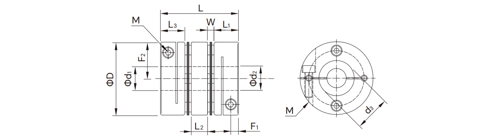
1. Structural Analysis:
Double diaphragm assembly: Two independent sets of diaphragms compensate for deviations at both connection points, breaking down and managing complex combined deviations.
Intermediate shaft: As a rigid connecting body, its length can be customized as needed, and is crucial for handling long spans (where the motor and load are far apart).
2. Core Performance:
Ultra-large compensation capacity: Its allowable angular deviation is typically more than twice that of comparable SMP couplings, and the axial compensation capacity is also significantly increased.
Maintenance and balancing: All-metal, maintenance-free. The intermediate shaft and end components can be individually dynamically balanced to ensure overall smooth high-speed operation.
3. Selection Criteria:
The DMP series should be prioritized when the application involves the following situations:
Large equipment base span, making it difficult to ensure high coaxiality during installation.
Significant thermal expansion during equipment operation, leading to large changes in shaft end position.
Risk of unavoidable soft foundation settlement or structural deformation.
Applications
The DMP series is an expert in solving the following challenging connection problems:
Large gantry machine tools: Connecting the ends of long-stroke lead screws far from the motor, compensating for bed deformation and installation errors.
Ships and heavy machinery: Connecting the engine and gearbox, dealing with foundation deformation and significant thermal displacement.
Large pumps and fans: Long shaft connection between the motor and pump body, compensating for installation misalignment and thermal expansion and contraction.
Special equipment and test benches: Transmission connections requiring simulation or tolerance of large displacement conditions. The DMP Series Double Diaphragm Coupling is a testament to engineering ingenuity. Through a clever "divide and conquer" strategy, it transforms complex large-deviation problems into two easily manageable small deviations. It's not just a coupling; it's a systematic compensation solution for challenging connection conditions. Choosing the DMP series means you are directly addressing and perfectly resolving the unavoidable mechanical deviations in your equipment, providing the highest level of assurance for long-term stable operation, low maintenance costs, and exceptional reliability.
Parameters
| Model No. |
d1/d2 pore size |
D
(mm) |
L
(mm) |
L1
(mm) |
L3
(mm) |
W
(mm) |
L2
(mm) |
d3
(mm) |
Screw size M |
Tightening torque (N.m) |
Rated torque (N.m) |
Maximum torque (N.m) |
Maximum speed (RPM) |
Moment of inertia (kg·m²) |
Static torsional stiffness (N.m/rad) |
Permissible eccentricity (mm) |
Permissible deviation (° ) |
Axial runout (mm) |
| Min (mm) |
Max (mm) |
|
| DMP-D19L26 |
3 |
8 |
19 |
26 |
9 |
9 |
1 |
6 |
8 |
M3 |
0.8 |
2 |
4 |
10000 |
6.7*10-7 |
580 |
0.02 |
1 |
±0.09 |
| DMP-D19L29 |
3 |
8 |
19 |
29 |
9 |
12 |
1 |
6 |
8 |
M3 |
0.8 |
2 |
4 |
10000 |
6.7*10-7 |
580 |
0.02 |
1 |
±0.09 |
| DMP-D19L32 |
3 |
8 |
19 |
32 |
12 |
12 |
1 |
6 |
8 |
M3 |
0.8 |
2 |
4 |
10000 |
6.7*10-7 |
580 |
0.02 |
1 |
±0.09 |
| DMP-D19L35 |
3 |
8 |
19 |
35 |
12 |
12 |
1 |
9 |
8 |
M3 |
0.8 |
2 |
4 |
10000 |
6.7*10-7 |
580 |
0.02 |
1 |
±0.09 |
| DMP-D26L35 |
4 |
10 |
26 |
35 |
12 |
12 |
2 |
7 |
10 |
M3 |
1.5 |
3.5 |
7 |
10000 |
1.8*10-6 |
1250 |
0.02 |
1 |
±0.1 |
| DMP-D26L38 |
4 |
10 |
26 |
38 |
12 |
15 |
2 |
7 |
10 |
M3 |
1.5 |
3.5 |
7 |
10000 |
1.8*10-6 |
1250 |
0.02 |
1 |
±0.1 |
| DMP-D26L41 |
4 |
10 |
26 |
41 |
15 |
15 |
2 |
7 |
10 |
M3 |
1.5 |
3.5 |
7 |
10000 |
1.8*10-6 |
1250 |
0.02 |
1 |
±0.1 |
| DMP-D26L44 |
4 |
10 |
26 |
44 |
15 |
15 |
2 |
10 |
10 |
M3 |
1.5 |
3.5 |
7 |
10000 |
1.8*10-6 |
1250 |
0.02 |
1 |
±0.1 |
| DMP-D32L41 |
4 |
15 |
32 |
41 |
13.5 |
13.5 |
2 |
10 |
16 |
M3 |
1.5 |
5 |
10 |
10000 |
7.2*10-6 |
1800 |
0.02 |
1 |
±0.14 |
| DMP-D32L44 |
4 |
15 |
32 |
44 |
13.5 |
16.5 |
2 |
10 |
16 |
M3 |
1.5 |
5 |
10 |
10000 |
7.2*10-6 |
1800 |
0.02 |
1 |
±0.14 |
| DMP-D32L47 |
4 |
15 |
32 |
47 |
16.5 |
16.5 |
2 |
10 |
16 |
M3 |
1.5 |
5 |
10 |
10000 |
7.2*10-6 |
1800 |
0.02 |
1 |
±0.14 |
| DMP-D32L50 |
4 |
15 |
32 |
50 |
16.5 |
16.5 |
2 |
13 |
16 |
M3 |
1.5 |
5 |
10 |
10000 |
7.2*10-6 |
1800 |
0.02 |
1 |
±0.14 |
| DMP-D34L45 |
4 |
14 |
34 |
45 |
15 |
15 |
2 |
11 |
16 |
M4 |
2.5 |
6 |
12 |
10000 |
7.2*10-6 |
1800 |
0.02 |
1 |
±0.18 |
| DMP-D34L50 |
4 |
14 |
34 |
50 |
15 |
20 |
2 |
11 |
16 |
M4 |
2.5 |
6 |
12 |
10000 |
7.2*10-6 |
1800 |
0.02 |
1 |
±0.18 |
| DMP-D34L55 |
4 |
14 |
34 |
55 |
20 |
20 |
2 |
11 |
16 |
M4 |
2.5 |
6 |
12 |
10000 |
7.2*10-6 |
1800 |
0.02 |
1 |
±0.18 |
| DMP-D34L60 |
4 |
14 |
34 |
60 |
20 |
20 |
2 |
16 |
16 |
M4 |
2.5 |
6 |
12 |
10000 |
7.2*10-6 |
1800 |
0.02 |
1 |
±0.18 |
| DMP-D39L49 |
6 |
19 |
39 |
49 |
15 |
15 |
4 |
11 |
19 |
M4 |
2.5 |
8 |
16 |
10000 |
1.8*10-5 |
3700 |
0.02 |
1 |
±0.18 |
| DMP-D39L54 |
6 |
19 |
39 |
54 |
15 |
20 |
4 |
11 |
19 |
M4 |
2.5 |
8 |
16 |
10000 |
1.8*10-5 |
3700 |
0.02 |
1 |
±0.18 |
| DMP-D39L59 |
6 |
19 |
39 |
59 |
20 |
20 |
4 |
11 |
19 |
M4 |
2.5 |
8 |
16 |
10000 |
1.8*10-5 |
3700 |
0.02 |
1 |
±0.18 |
| DMP-D39L64 |
6 |
19 |
39 |
64 |
20 |
20 |
4 |
16 |
19 |
M4 |
2.5 |
8 |
16 |
10000 |
1.8*10-5 |
3700 |
0.02 |
1 |
±0.18 |
| DMP-D44L50 |
8 |
22 |
44 |
50 |
15.5 |
15.5 |
4 |
11 |
22 |
M5 |
2.5 |
18 |
36 |
10000 |
2.8*10-5 |
3700 |
0.02 |
1 |
±0.18 |
| DMP-D44L55 |
8 |
22 |
44 |
55 |
15.5 |
20.5 |
4 |
11 |
22 |
M5 |
2.5 |
18 |
36 |
10000 |
2.8*10-5 |
3700 |
0.02 |
1 |
±0.18 |
| DMP-D44L60 |
8 |
22 |
44 |
60 |
20.5 |
20.5 |
4 |
11 |
22 |
M5 |
2.5 |
18 |
36 |
10000 |
2.8*10-5 |
3700 |
0.02 |
1 |
±0.18 |
| DMP-D44L65 |
8 |
22 |
44 |
65 |
20.5 |
20.5 |
4 |
16 |
22 |
M5 |
2.5 |
18 |
36 |
10000 |
2.8*10-5 |
3700 |
0.02 |
1 |
±0.18 |
| DMP-D50L57 |
8 |
26 |
50 |
57 |
18 |
18 |
5 |
11 |
26 |
M5 |
7 |
18 |
36 |
10000 |
2.5*10-5 |
3700 |
0.02 |
1 |
±0.2 |
| DMP-D50L65 |
8 |
26 |
50 |
65 |
18 |
26 |
5 |
11 |
26 |
M5 |
7 |
18 |
36 |
10000 |
2.5*10-5 |
3700 |
0.02 |
1 |
±0.2 |
| DMP-D50L73 |
8 |
26 |
50 |
73 |
26 |
26 |
5 |
11 |
26 |
M5 |
7 |
18 |
36 |
10000 |
2.5*10-5 |
3700 |
0.02 |
1 |
±0.2 |
| DMP-D50L81 |
8 |
26 |
50 |
81 |
26 |
26 |
5 |
19 |
26 |
M5 |
7 |
18 |
36 |
10000 |
2.5*10-5 |
3700 |
0.02 |
1 |
±0.2 |
| DMP-D56L63 |
10 |
30 |
56 |
63 |
20 |
20 |
5 |
13 |
29 |
M5 |
7 |
35 |
70 |
10000 |
1.0*10-4 |
8400 |
0.02 |
1 |
±0.2 |
| DMP-D56L71 |
10 |
30 |
56 |
71 |
20 |
28 |
5 |
13 |
29 |
M5 |
7 |
35 |
70 |
10000 |
1.0*10-4 |
8400 |
0.02 |
1 |
±0.2 |
| DMP-D56L79 |
10 |
30 |
56 |
79 |
28 |
28 |
5 |
13 |
29 |
M5 |
7 |
35 |
70 |
10000 |
1.0*10-4 |
8400 |
0.02 |
1 |
±0.2 |
| DMP-D56L87 |
10 |
30 |
56 |
87 |
28 |
28 |
5 |
21 |
29 |
M5 |
7 |
35 |
70 |
10000 |
1.0*10-4 |
8400 |
0.02 |
1 |
±0.2 |
| DMP-D68L74 |
12 |
35 |
68 |
74 |
24 |
24 |
6 |
14 |
39 |
M6 |
12 |
65 |
130 |
9000 |
1.5*10-4 |
11500 |
0.02 |
1 |
±0.2 |
| DMP-D68L82 |
12 |
35 |
68 |
82 |
24 |
32 |
6 |
14 |
39 |
M6 |
12 |
65 |
130 |
9000 |
1.5*10-4 |
11500 |
0.02 |
1 |
±0.2 |
| DMP-D68L90 |
12 |
35 |
68 |
90 |
32 |
32 |
6 |
14 |
39 |
M6 |
12 |
65 |
130 |
9000 |
1.5*10-4 |
11500 |
0.02 |
1 |
±0.2 |
| DMP-D68L98 |
12 |
35 |
68 |
98 |
32 |
32 |
6 |
22 |
39 |
M6 |
12 |
65 |
130 |
9000 |
1.5*10-4 |
11500 |
0.02 |
1 |
±0.2 |
| DMP-D82L98 |
14 |
45 |
82 |
98 |
30 |
30 |
8 |
22 |
44 |
M8 |
16 |
100 |
200 |
8000 |
1.8*10-4 |
14500 |
0.02 |
1 |
±0.2 |
| DMP-D82L108 |
14 |
45 |
82 |
108 |
30 |
40 |
8 |
22 |
44 |
M8 |
16 |
100 |
200 |
8000 |
1.8*10-4 |
14500 |
0.02 |
1 |
±0.2 |
| DMP-D82L118 |
14 |
45 |
82 |
118 |
40 |
40 |
8 |
22 |
44 |
M8 |
16 |
100 |
200 |
8000 |
1.8*10-4 |
14500 |
0.02 |
1 |
±0.2 |
| DMP-D82L128 |
14 |
45 |
82 |
128 |
40 |
40 |
8 |
32 |
44 |
M8 |
16 |
100 |
200 |
8000 |
1.8*10-4 |
14500 |
0.02 |
1 |
±0.2 |
| DMP-D94L100 |
19 |
50 |
94 |
100 |
30 |
30 |
9 |
22 |
48 |
M10 |
16 |
165 |
320 |
5000 |
1.2*10-4 |
40000 |
0.02 |
1 |
±0.2 |
| DMP-D94L110 |
19 |
50 |
94 |
110 |
30 |
40 |
9 |
22 |
48 |
M10 |
16 |
165 |
320 |
5000 |
1.2*10-4 |
40000 |
0.02 |
1 |
±0.2 |
| DMP-D94L120 |
19 |
50 |
94 |
120 |
40 |
40 |
9 |
22 |
48 |
M10 |
16 |
165 |
320 |
5000 |
1.2*10-4 |
40000 |
0.02 |
1 |
±0.2 |
| DMP-D94L130 |
19 |
50 |
94 |
130 |
40 |
40 |
9 |
32 |
48 |
M10 |
16 |
165 |
320 |
5000 |
1.2*10-4 |
40000 |
0.02 |
1 |
±0.2 |
| DMP-D104L102 |
20 |
55 |
104 |
102 |
30 |
30 |
10 |
22 |
48 |
M10 |
16 |
235 |
470 |
4000 |
1.8*10-3 |
80000 |
0.02 |
1 |
±0.2 |
| DMP-D104L112 |
20 |
55 |
104 |
112 |
30 |
40 |
10 |
22 |
48 |
M10 |
16 |
235 |
470 |
4000 |
1.8*10-3 |
80000 |
0.02 |
1 |
±0.2 |
| DMP-D104L122 |
20 |
55 |
104 |
122 |
40 |
40 |
10 |
22 |
48 |
M10 |
16 |
235 |
470 |
4000 |
1.8*10-3 |
80000 |
0.02 |
1 |
±0.2 |
| DMP-D104L132 |
20 |
55 |
104 |
132 |
40 |
40 |
10 |
32 |
48 |
M10 |
16 |
235 |
470 |
4000 |
1.8*10-3 |
80000 |
0.02 |
1 |
±0.2 |
Drawings
 English
 Português
 русский
 Español
 The LMHC-L-UU series linear bearing is a high-performance linear bearing that combine...
 The LMFC/LMKC series linear bearing is a special type of linear bearing with a flange...
 The LMHP-L-UU series linear bearing is a pinnacle of design, combining four key featu...
 The LMFP-L/LMKP-L series linear bearings are linear bearings that combine three core ...
 The LMHP-UU series linear bearing is a high-end linear bearing that combines three ke...


