Main System Components and Selection
1. Core Components:
Shaft: High-frequency hardened and chrome-plated hard shaft, with high surface hardness and wear resistance. (S45C and GCr15 materials are available for the shaft) Available in various diameters (e.g., φ12, φ16, φ20, φ50mm) and tolerance grades (e.g., g6, h7).
Linear Bearing: Standard linear ball bearing, available in metal housing type (LM OP series) and engineering plastic housing type (LM OP series), some with sealing rings for dust protection.
Support Unit: Includes fixed-end support base, floating-end support base, and intermediate support ring, used to fix the shaft and ensure its straightness.
2. Configuration Diversity:
Single-axis support: Basic form.
Dual-axis parallel support: Significantly improves torque resistance and load stability.
Matching linear bearing unit: The linear bearing is pre-installed in a block-shaped housing with mounting holes, forming a ready-to-use module for easier installation.
3. Selection Key Points:
Determine Load and Layout: Calculate the load, decide whether to use single-axis or dual-axis support, and plan the shaft length and support point positions.
Select Shaft Specifications: Choose the diameter based on load and rigidity requirements, select the length based on the stroke, and consider the support spacing to prevent shaft bending.
Select Bearing Type: Standard type for general environments, sealed type for dusty environments, and stainless steel type for corrosion resistance.
Main Applications
Thanks to its cost-effectiveness and flexibility, the SBR series is used in almost all industrial fields:
Factory automation: Conveyor line push rods, material stops, automatic door slides, simple robotic arms.
Packaging and printing equipment: Paper feeding mechanisms, ink cartridge moving platforms, packaging machine folding mechanisms.
Medical and office equipment: Hospital bed adjustment mechanisms, printer head movement, scanner slides.
Agricultural and textile machinery: Seed drill furrow opener adjustment, textile machine spindle traverse devices.
Any application requiring reliable, low-cost linear guidance.
The SBR series cylindrical guide rail system is a timeless classic design in the field of linear motion. It may not have the most impressive performance parameters, but it is undoubtedly the most widely used, trustworthy, and cost-effective basic solution. Choosing the SBR series means choosing a reliable, economical, and highly flexible technological path, enabling you to incorporate reliable linear motion functions into your equipment with minimal risk and investment. It is a solid foundation for quickly transforming creative ideas into stable prototypes and mass-produced equipment.
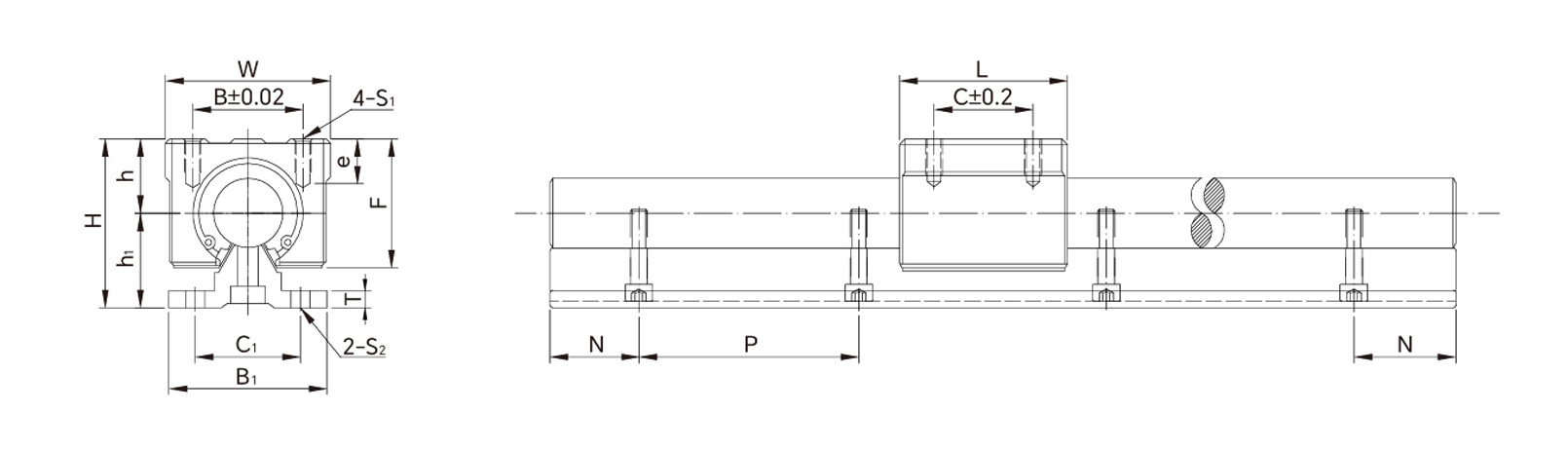
Parameters
| Model No. |
Shaft
Diameter |
Dimensions of
Assembly (mm) |
Dimensions of Block(mm) |
Dimensions of Rail(mm) |
Basic Load
Rating |
Weight |
|
| Rail |
Block |
H |
W |
e |
h |
F |
W |
L |
B |
C |
S1 |
h1 |
B1 |
C1 |
P |
T |
S2 |
dyn.c |
stat.co |
slider
kg/pc |
guide rail
kg/m |
| SBRC10 |
SBR10UU |
φ10 |
33 |
36 |
10 |
15 |
24 |
36 |
32 |
25 |
20 |
M5 |
18 |
22 |
22 |
100 |
4 |
φ4.5 |
372 |
549 |
0.065 |
1.2 |
| SBR10LUU |
68 |
46 |
774 |
1020 |
0.13 |
| SBR12G |
SBR12UU |
φ12 |
39.5 |
40 |
10 |
17 |
27.6 |
40 |
39 |
28 |
26 |
M5 |
22.5 |
30 |
22 |
100 |
4 |
φ4.5 |
500 |
770 |
0.1 |
1.6 |
| SBR12LUU |
75 |
50 |
1020 |
1548 |
0.2 |
| SBRC12 |
SBR12UU |
φ12 |
36 |
40 |
10 |
17 |
27.6 |
40 |
39 |
28 |
26 |
M5 |
19 |
32 |
22 |
100 |
4 |
φ4.5 |
500 |
770 |
0.1 |
1.6 |
| SBR12LUU |
75 |
50 |
1020 |
1548 |
0.2 |
| SBRC13 |
SBR13UU |
φ13 |
36.5 |
40 |
10 |
17 |
27.6 |
40 |
39 |
28 |
26 |
M5 |
19.5 |
32 |
22 |
100 |
4 |
φ4.5 |
510 |
784 |
0.1 |
1.8 |
| SBRC16 |
SBR16UU |
φ16 |
45 |
45 |
12 |
20 |
33 |
45 |
45 |
32 |
30 |
M5 |
25 |
40 |
30 |
150 |
5 |
φ5.5 |
774 |
1180 |
0.15 |
2.6 |
| SBR16LUU |
85 |
60 |
1548 |
2360 |
0.3 |
| SBRC20 |
SBR20UU |
φ20 |
50 |
48 |
12 |
23 |
39 |
48 |
50 |
35 |
35 |
M6 |
27 |
45 |
30 |
150 |
5 |
φ5.5 |
882 |
1370 |
0.2 |
3.6 |
| SBR20LUU |
96 |
70 |
1764 |
2740 |
0.4 |
| SBRC25 |
SBR25UU |
φ25 |
60 |
60 |
12 |
27 |
47 |
60 |
65 |
40 |
40 |
M6 |
33 |
55 |
35 |
200 |
6 |
φ6.6 |
980 |
1570 |
0.45 |
5.4 |
| SBR25LUU |
130 |
100 |
1960 |
3140 |
0.9 |
| SBRC30 |
SBR30UU |
φ30 |
70 |
70 |
18 |
33 |
56 |
70 |
70 |
50 |
50 |
M8 |
37 |
60 |
40 |
200 |
7 |
φ6.6 |
1570 |
2740 |
0.63 |
7.5 |
| SBR30LUU |
140 |
110 |
3140 |
5480 |
1.26 |
| SBRC35 |
SBR35UU |
φ35 |
80 |
80 |
18 |
37 |
63 |
80 |
80 |
55 |
55 |
M8 |
43 |
65 |
45 |
200 |
8 |
φ9 |
1670 |
3140 |
0.92 |
10 |
| SBR35LUU |
160 |
120 |
3440 |
6280 |
1.8 |
| SBRC40 |
SBR40UU |
φ40 |
90 |
90 |
20 |
42 |
72 |
90 |
90 |
65 |
65 |
M10 |
48 |
75 |
55 |
200 |
9 |
φ9 |
2160 |
4020 |
1.33 |
13.2 |
| SBR40LUU |
175 |
140 |
4320 |
8040 |
2.66 |
| SBRC50 |
SBR50UU |
φ50 |
115 |
120 |
20 |
53 |
92 |
120 |
110 |
94 |
80 |
M10 |
62 |
95 |
70 |
200 |
11 |
φ11 |
3820 |
7940 |
3 |
20.7 |
| SBR50LUU |
215 |
160 |
M12 |
7640 |
15880 |
6 |
Drawings
 English
 Português
 русский
 Español
 The LMHC-L-UU series linear bearing is a high-performance linear bearing that combine...
 The LMFC/LMKC series linear bearing is a special type of linear bearing with a flange...
 The LMHP-L-UU series linear bearing is a pinnacle of design, combining four key featu...
 The LMFP-L/LMKP-L series linear bearings are linear bearings that combine three core ...
 The LMHP-UU series linear bearing is a high-end linear bearing that combines three ke...


