Main Technical Parameters and Selection
1. Design Philosophy: Applies the "area moment of inertia" principle, significantly increasing the moment of inertia of the cross-section by increasing the width, thereby achieving a qualitative leap in resistance to bending and torsion within a small vertical space.
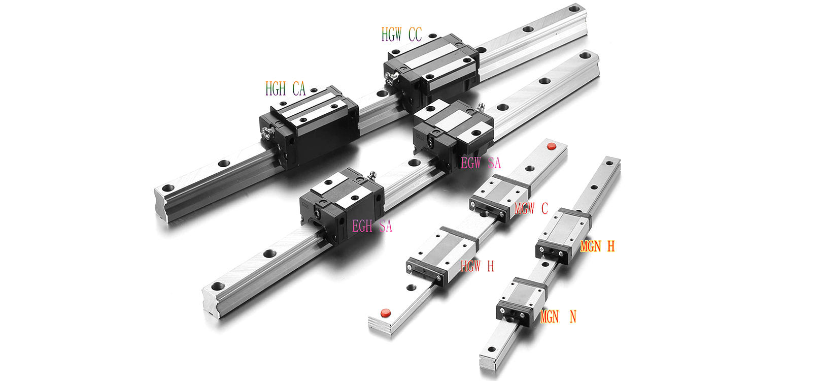
2. Specification Range: Available in specifications such as MGW7, MGW9, MGW12, MGW15, etc., where the number represents the guide rail width (unit: mm). For the same numerical specification (e.g., MGN9 and MGW9), the MGW series has a larger slider width and guide rail width.
3. Key Selection Criteria:
Height is still the primary constraint: Confirm the maximum allowable total installation height for the equipment.
Prioritize wide-body design: Within the allowable height range, choosing the MGW series instead of the MGN series will directly result in significant performance improvements.
Verify load and torque: If the application involves significant eccentric forces or requires extremely high motion smoothness, the MGW series is a more reliable choice.
Applications
The MGW-C/H series mini linear guide is the ideal choice for the following top-tier miniature equipment with demanding requirements for both space and performance:
Ultra-precision optical systems: Miniature adjustment mechanisms for space telescopes, micro-motion units for mask stages in high-end lithography machines.
High-end semiconductor inspection: Scanning stages for nanoscale morphology measuring instruments (such as atomic force microscopes AFM), precision motion axes for wafer defect detection equipment.
Biomedical engineering: Specimen stages for confocal microscopes, high-rigidity miniature arms for cell surgery robots. Precision Manufacturing and Micro-Assembly: Precision placement equipment for miniature components (such as MEMS), and active alignment platforms for fiber optic arrays.
The MGW-C/H series mini linear guide represents the evolution of miniature linear guidance technology from simply "solving the problem of existence" to "pursuing excellence." It demonstrates that even within millimeters, engineers can still endow components with powerful mechanical performance through ingenious design. Choosing the MGW series means your miniature device design not only pursues compactness but also prioritizes inherent robustness, stability, and reliability. It is a strategic cornerstone for building high-performance precision motion systems in a confined space, helping your products establish a solid hardware advantage in cutting-edge technological competition.
Parameters
Model
No. |
Dimensions
of Assembly
(mm) |
Dimensions of Block
(mm) |
Dimensions of Rail
(mm) |
Mounting
Bolt for
Rail |
Basic
Dynamic
Load
Rating |
Basic
Static
Load
Rating |
Static Rated
Moment(kgf.m) |
Weight |
| H |
H1 |
N |
W |
B |
B1 |
C |
L1 |
L |
G |
Gn |
MxI |
H2 |
WR |
WB |
HR |
D |
h |
d |
P |
E |
(mm) |
C(KN) |
C0(KN) |
MR
N-m |
MP
N-m |
MY
N-m |
block
kg |
Rail
kg/m |
| MGW 5C |
6.5 |
1.5 |
3.5 |
17 |
13 |
2 |
- |
14.1 |
20.5 |
- |
Φ0.8 |
M2.5x1.5 |
1 |
10 |
- |
4 |
5.5 |
1.6 |
3 |
20 |
5 |
M2.5x7 |
0.68 |
1.18 |
5.5 |
2.7 |
2.7 |
0.016 |
0.34 |
| MGW 5CL |
- |
8.5 |
6.5 |
M3-THRU |
| MGW 7C |
9 |
1.9 |
5.5 |
25 |
19 |
3 |
10 |
21 |
31.2 |
- |
Φ1.2 |
M3x3 |
1.85 |
14 |
- |
5.2 |
6 |
3.2 |
3.5 |
30 |
10 |
M3x6 |
1.37 |
2.06 |
15.70 |
7.14 |
7.14 |
0.020 |
0.51 |
| MGW 7H |
19 |
30.8 |
41 |
1.77 |
3.14 |
23.45 |
15.53 |
15.53 |
0.029 |
| MGW 9C |
12 |
2.9 |
6 |
30 |
21 |
4.5 |
12 |
27.5 |
39.3 |
- |
Φ1.2 |
M3x3 |
2.4 |
18 |
- |
7 |
6 |
4.5 |
3.5 |
30 |
10 |
M3x8 |
2.75 |
4.12 |
40.12 |
18.96 |
18.96 |
0.040 |
0.91 |
| MGW 9H |
23 |
3.5 |
24 |
38.5 |
50.7 |
3.43 |
5.89 |
54.54 |
34.00 |
34.00 |
0.057 |
| MGW 12C |
14 |
3.4 |
8 |
40 |
28 |
6 |
15 |
31.3 |
46.1 |
- |
Φ1.2 |
M3x3.6 |
2.8 |
24 |
- |
8.5 |
8 |
4.5 |
4.5 |
40 |
15 |
M4x8 |
3.92 |
5.59 |
70.34 |
27.80 |
27.80 |
0.071 |
1.49 |
| MGW 12H |
28 |
45.6 |
60.4 |
5.10 |
8.24 |
102.70 |
57.37 |
57.37 |
0.103 |
| MGW 15C |
16 |
3.4 |
9 |
60 |
45 |
7.5 |
20 |
38 |
54.8 |
5.2 |
M3 |
M4x4.2 |
3.2 |
42 |
23 |
9.5 |
8 |
4.5 |
4.5 |
40 |
15 |
M4x10 |
6.77 |
9.22 |
199.34 |
56.66 |
56.66 |
0.143 |
2.86 |
| MGW 15H |
35 |
57 |
73.8 |
8.93 |
13.38 |
299.01 |
122.60 |
122.60 |
0.215 |
Drawings

Supports Product Combination Selection
Production Capacity
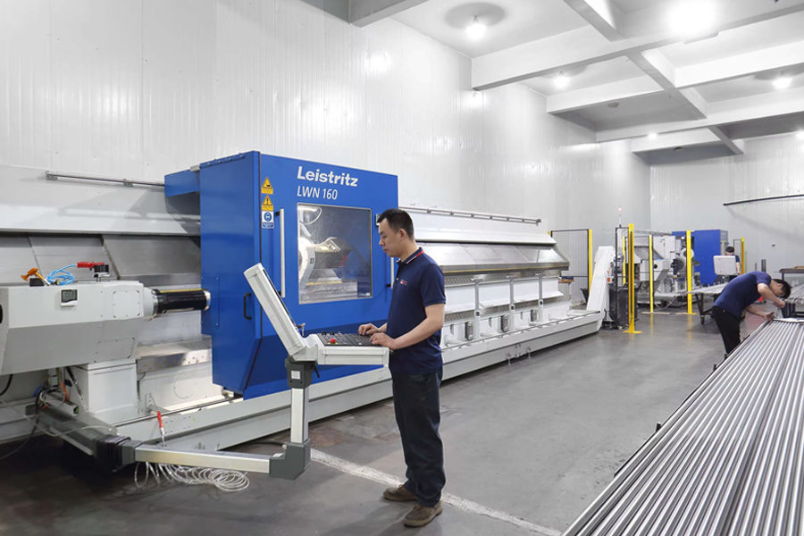 |
Cyclone Milling Machines
LWN160-6000mm Leistritz Cyclone milling machines imported directly from
Germany, the ball screw shaft precision can be C3, C5, and C7 the max length
can be 7000mm |
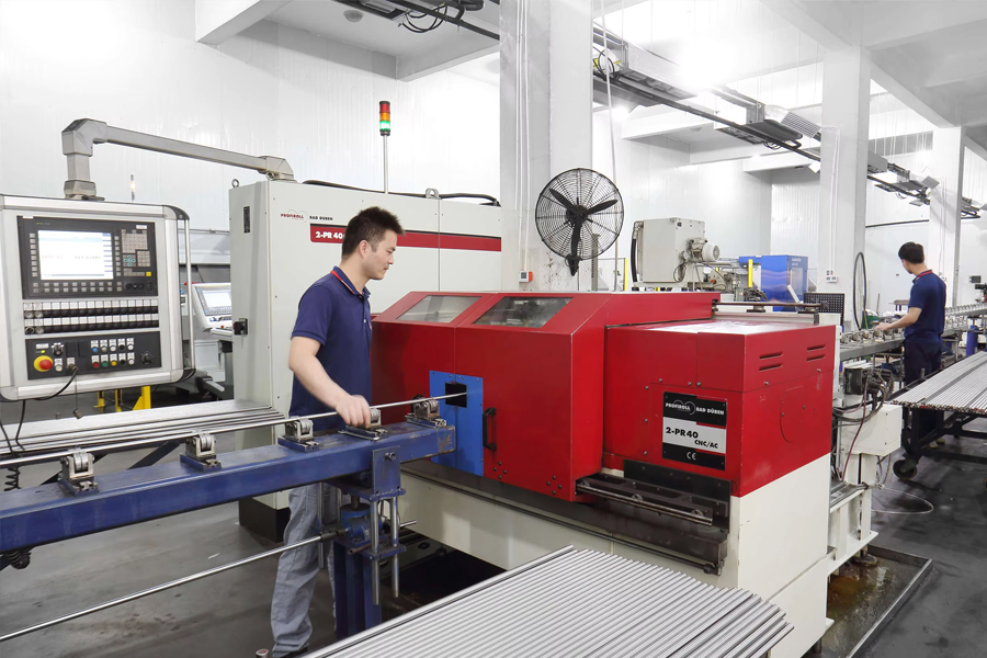
Rolled Thread CNC Machines
PR-40CNC Profiroll rolled thread ball screw machines imported directly from
Germany the ball screw shaft precision can be C5, C7 -C10 |
|
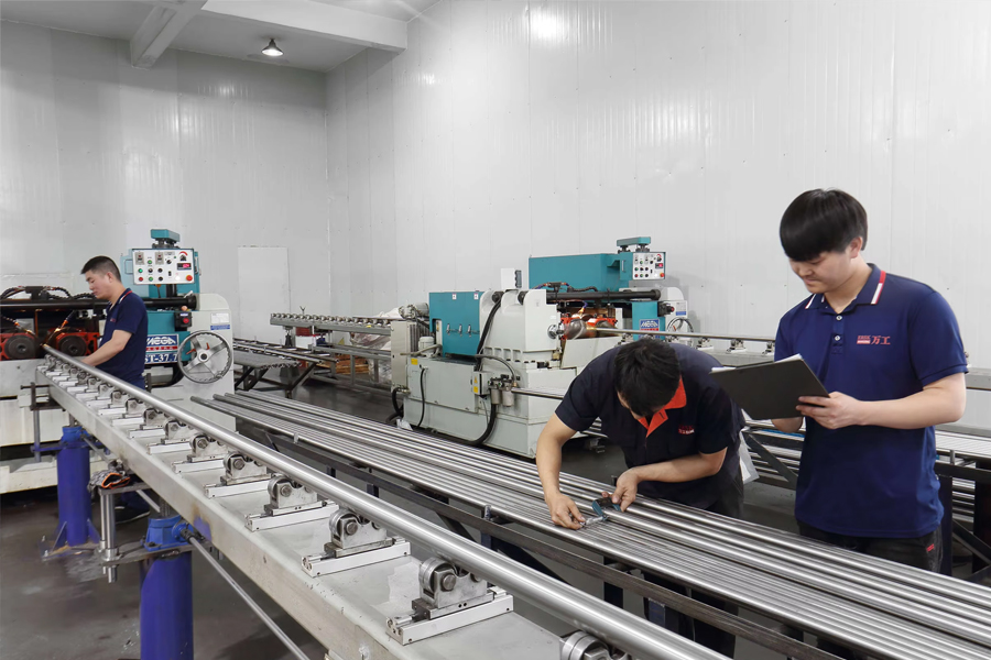 |
Rolled Thread CNC Machines
ST-20.2 and ST-347.7 rolled thread ball screw machines from TaiWan.
The ball screw shaft precision can be C7 - C10 |
Ball Screw Assembly Workshop
We conduct nut assembly in a constant temperature workshop, all workers
having decades of work experience and zero clearance between the screw
and nut. |
 |
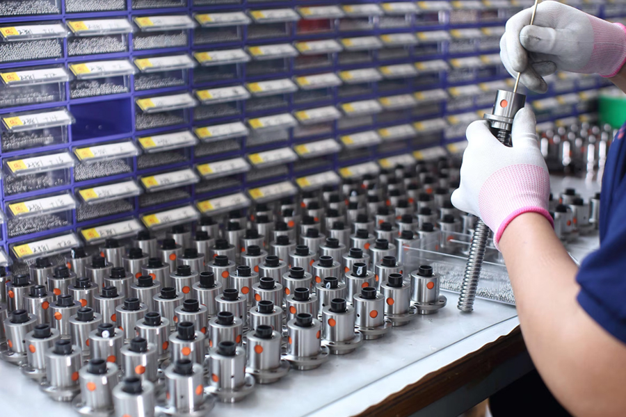 |
Ball Screw Assembly Workshop
One ball screw shaft matches one ball screw nut. Because each ball screw
shaft has a very tiny different tolerance. There are dozens of different
ball sizes for different screw shaft.
Our ball screw shaft and nut can be interchanged with the Taiwan
TBI ball screw shaft and nut very well. |
 English
 Português
 русский
 Español
 The LMHC-L-UU series linear bearing is a high-performance linear bearing that combine...
 The LMFC/LMKC series linear bearing is a special type of linear bearing with a flange...
 The LMHP-L-UU series linear bearing is a pinnacle of design, combining four key featu...
 The LMFP-L/LMKP-L series linear bearings are linear bearings that combine three core ...
 The LMHP-UU series linear bearing is a high-end linear bearing that combines three ke...


