Main Technical Parameters and Design
1. Locking Structure Principle: Uses a side-angled hole or bottom countersunk hole design, secured with internal hexagon flat-head screws. During installation, the screw heads are recessed into the slider body and do not protrude.
2. Performance Retention: As a high-assembly type, it fully inherits the high rigidity, high load capacity, and high precision performance of high-assembly guide rails, only changing the mounting interface.
3. Installation Steps:
First, fix the guide rail to the machine bed.
Align and place the load platform on the slider.
From the side or through pre-drilled holes in the load platform, use an extended hex wrench to diagonally insert into the locking holes of the slider to complete the fastening.
Applications
The High Assembly Bottom Lock HGR-T Series Linear Guideway is the preferred choice for the following structurally innovative and space-optimized equipment:
High-speed and high-precision machine tools: Tool magazine movement mechanisms of vertical machining centers, worktables of precision grinding machines, enabling an integrated design without top protrusions.
Semiconductor and panel equipment: In-chamber manipulators of lithography machines and OLED evaporation machines, requiring no exposed screws in vacuum or clean environments.
Medical and laboratory equipment: Motion platforms of automated analyzers and cell culture equipment, facilitating cleaning and preventing contamination.
Industrial robots: Slider for the seventh axis (ground rail) of robots, allowing the robot base to be directly mounted as the load platform without the need for additional adapter plates.
The High Assembly Bottom Lock HGR-T Series Linear Guideway is not just an improvement of a component, but a liberation of design thinking. It frees engineers from the traditional constraint of "having to leave top clearance for screws," opening up new possibilities for more compact, integrated, and streamlined equipment designs. Choosing the HGR-T series means you are pursuing the ultimate optimization and innovation in equipment design, striving to create cutting-edge products that are exemplary in performance, reliability, and space utilization. It represents a significant step forward in linear motion technology to meet the demands of future high-end equipment.
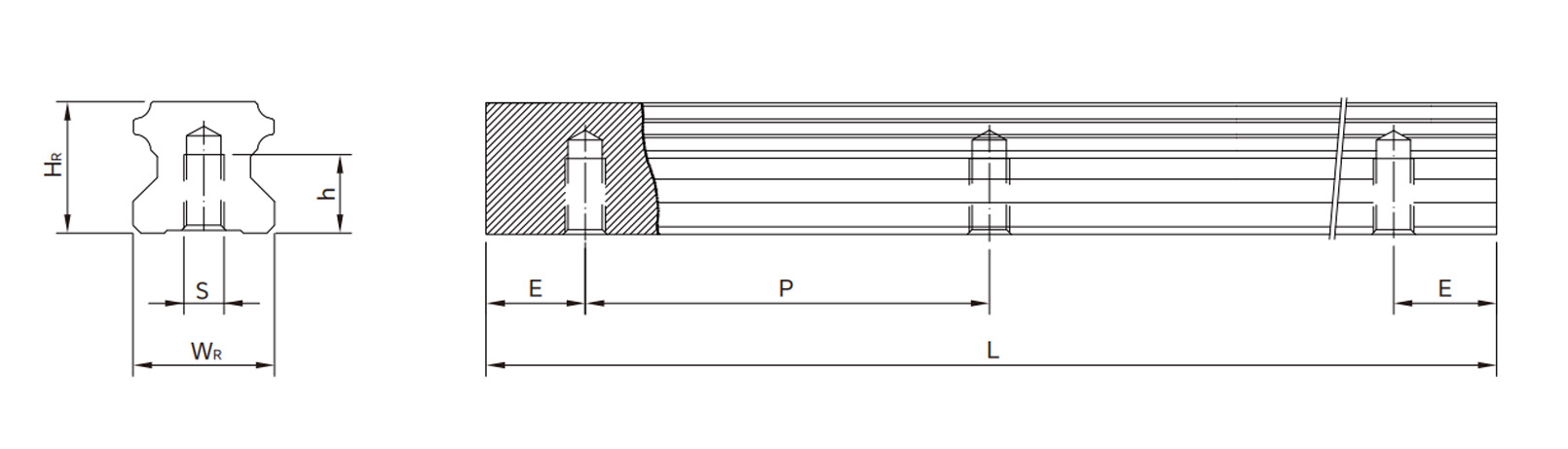
Parameters
| Model No. |
Dimensions of Rail (mm) |
Weight |
WR
15 |
HR
15 |
S |
h |
P |
E |
(kg/m) |
| HGR15T |
15 |
15 |
M5x0.8P |
8 |
60 |
20 |
1.48 |
|
| HGR20T |
20 |
17.5 |
M6x1P |
10 |
60 |
20 |
2.29 |
| HGR25T |
23 |
22 |
M6x1P |
12 |
60 |
20 |
3.35 |
|
| HGR30T |
28 |
26 |
M8x1.25P |
15 |
80 |
20 |
4.67 |
| HGR35T |
34 |
29 |
M8x1.25P |
17 |
80 |
20 |
6.51 |
| HGR45T |
45 |
38 |
M12x1.75P |
24 |
105 |
22.5 |
10.87 |
| HGR55T |
53 |
44 |
M14x2P |
24 |
120 |
30 |
15.67 |
| HGR65T |
63 |
53 |
M20x2.5P |
30 |
150 |
35 |
21.73 |
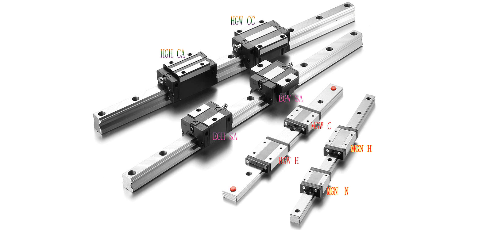
Drawings
Supports Product Combination Selection
Production Capacity
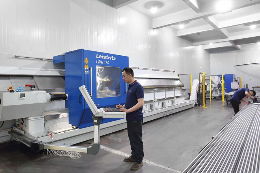 |
Cyclone Milling Machines
LWN160-6000mm Leistritz Cyclone milling machines imported directly from
Germany, the ball screw shaft precision can be C3, C5, and C7 the max length
can be 7000mm |
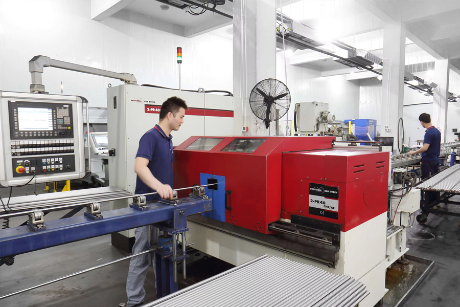
Rolled Thread CNC Machines
PR-40CNC Profiroll rolled thread ball screw machines imported directly from
Germany the ball screw shaft precision can be C5, C7 -C10 |
|
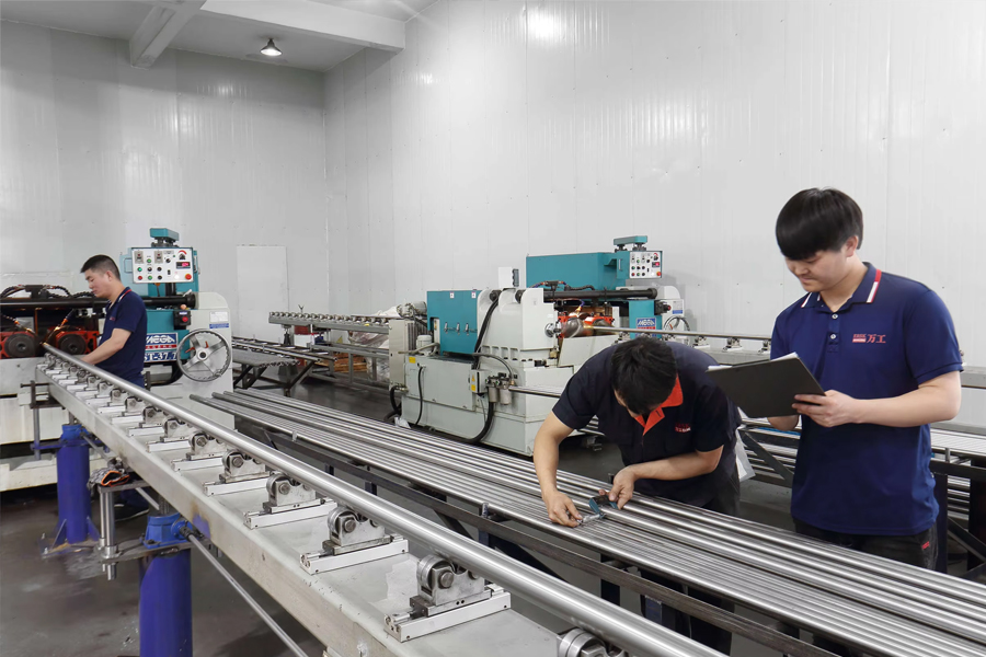 |
Rolled Thread CNC Machines
ST-20.2 and ST-347.7 rolled thread ball screw machines from TaiWan.
The ball screw shaft precision can be C7 - C10 |
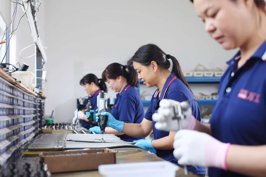
Ball Screw Assembly Workshop
We conduct nut assembly in a constant temperature workshop, all workers
having decades of work experience and zero clearance between the screw
and nut. |
 |
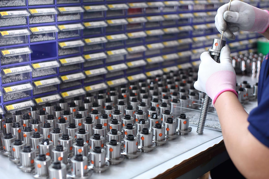 |
Ball Screw Assembly Workshop
One ball screw shaft matches one ball screw nut. Because each ball screw
shaft has a very tiny different tolerance. There are dozens of different
ball sizes for different screw shaft.
Our ball screw shaft and nut can be interchanged with the Taiwan
TBI ball screw shaft and nut very well. |
 English
 Português
 русский
 Español
 The LMHC-L-UU series linear bearing is a high-performance linear bearing that combine...
 The LMFC/LMKC series linear bearing is a special type of linear bearing with a flange...
 The LMHP-L-UU series linear bearing is a pinnacle of design, combining four key featu...
 The LMFP-L/LMKP-L series linear bearings are linear bearings that combine three core ...
 The LMHP-UU series linear bearing is a high-end linear bearing that combines three ke...


