| Product Features |
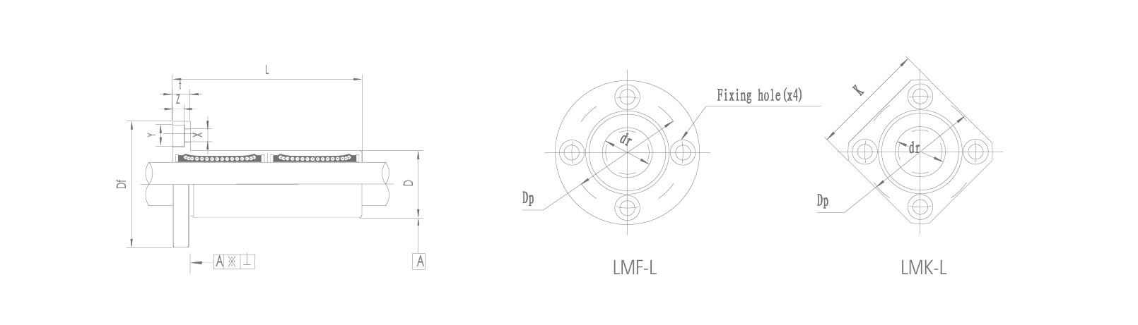
LMF-L-UU (Extended Round Flange Type) |
LMK-L-UU (Extended Flange Type) |
Core Selection Logic |
| Core Positioning |
An extended standard solution offering heavy-duty capacity, high rigidity and easy installation. |
An extended, reinforced solution designed for heavy-duty loads, high torque resistance and ultra-stable installation. |
Select the L-type for heavy loads; then choose either the F-type or K-type flange based on the torque requirement and available space. |
| Design Focus |
Round flange + extended bearing housing. Whilst providing easy installation, the extended design delivers a significant leap in load capacity and rigidity. |
Square/rectangular flange + extended bearing housing. The torque-resisting advantages of the flange combine with the high rigidity of the extended housing to create the ultimate cost-effective solution for handling the most complex loads. |
The ‘extended’ version enhances absolute rigidity, whilst the ‘flanged’ version optimises torque resistance; combining the two enables the unit to meet the most demanding challenges. |
| Key Advantages |
1. Significantly enhanced load capacity: The extension allows for a higher rated load.
2. Exceptional bending rigidity: Effectively suppresses deformation under cantilever loads.
3. Maintains ease of installation: Still utilises a one-piece flange mounting, eliminating the need for a bearing housing. |
1. Unrivalled resistance to overturning moments: The extended body and wide flange jointly provide unparalleled resistance to overturning and torsional loads.
2. Extremely smooth operation: The combination of long guides and a secure installation ensures minimal vibration.
3. Exceptional value for money: Achieves performance close to that of custom heavy-duty components at the cost and with the installation methods of standard parts. |
The LMF-L is designed for directional heavy loads, whilst the LMK-L is intended for complex torque-bearing heavy loads. |
| Structural Performance |
High. Provides extremely high bending rigidity in the extended direction, suitable for withstanding heavy axial loads. |
Exceptional. Delivers outstanding performance under multi-dimensional composite loads (particularly torque), maintaining stable load orientation. |
When the load is not only heavy but also has a centre of gravity offset from the axis, the LMK-L is the only option. |
| Installation and Space Requirements |
Installation is as straightforward as the LMF, but requires greater axial installation space to accommodate the extended body. |
Installation is as robust as the LMK, requiring a larger mounting surface and axial clearance. |
When selecting the extended version, it is essential to ensure that the equipment has sufficient installation length and space for flange mounting. |
| Typical Applications |
Tool arm guides for medium-sized vertical machining centres, push rod supports for heavy-duty logistics sorters, and lifting shafts for large-scale laboratory equipment. |
Drive slides for large laser cutting heads, sliders for heavy-duty robotic seventh axes (floor rails), and precision guide mechanisms for rear stopper systems on sheet metal bending machines. |
These applications are specifically tailored for heavy-duty and precision operations within the industrial sector. |
 English
 Português
 русский
 Español

 The LMHC-L-UU series linear bearing is a high-performance linear bearing that combine...
 The LMFC/LMKC series linear bearing is a special type of linear bearing with a flange...
 The LMHP-L-UU series linear bearing is a pinnacle of design, combining four key featu...
 The LMFP-L/LMKP-L series linear bearings are linear bearings that combine three core ...
 The LMHP-UU series linear bearing is a high-end linear bearing that combines three ke...


