Technical Service Depth: Drawings, Standards, and Quality Control
We ensure that every machining process is based on reliable data and standards:
1. Drawing Basis: We strictly follow international mainstream support unit interface standard drawings such as JIS B1192-1997 for machining. Customers can also provide customized drawings.
2. Core Parameter Control:
Fixed End: Strict control of shoulder diameter (e.g., j6 tolerance), end face runout (≤0.01mm), thread accuracy (6g), and keyway symmetry.
Support End: Precise control of mating journal diameter (e.g., h6 tolerance), length tolerance (±0.1mm), and circlip groove position and width.
3. Process and Quality Control: We use CNC multi-axis turning and milling machines to complete multi-feature machining in a single setup, ensuring coaxiality. Precision measuring instruments (such as CMMs) are used for full inspection or sampling, and inspection reports are provided.
Service Process
1. Requirement Confirmation: The customer provides the ball screw model, total length, and selected fixed and support end models (e.g., SFU1605-500mm, with BK12 and BF12).
2. Process Formulation: Standard drawings are retrieved or customer drawings are analyzed to generate machining programs and process cards.
3. Precision Machining: All features on both ends are machined on professional machine tools.
4. Cleaning and Inspection: After cleaning, key dimensions are inspected and recorded.
5. Delivery: We provide qualified products, and can provide simple installation diagrams or inspection data as needed.
Why Choose Our Integrated Machining Service?
Our service goes beyond simple "contract manufacturing"; it is your "performance insurance" and "efficiency engine" for building highly reliable linear motion systems. For equipment manufacturers (OEMs): Simplify your supply chain and improve assembly line efficiency. Receive ready-to-install ball screw assemblies, significantly reducing on-site measurement, debugging, and rework time, ensuring consistent quality of finished products.
For system integrators and end-users: Lower technical barriers and overall costs. Avoid the need to invest in precision machining equipment and skilled technicians, and prevent the costly consequences of self-machining errors, such as ball screw failure, bearing damage, or even complete machine malfunction. You pay for guaranteed results, not risk and uncertainty.
Choosing us means choosing professionalism, reliability, and peace of mind. We transform complex precision mechanical adaptation work into a set of standardized components that are quick to install and performance-guaranteed, allowing you to focus your energy on core design and innovation.
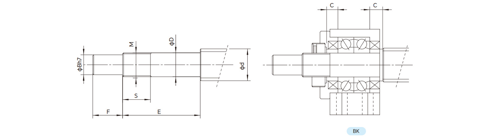
Parameters
| Model No. |
Shaft Support
OD |
Shaft Support OD |
|
Metric Screw Thread |
Ferrule Length |
|
| BK |
d |
D |
B |
E |
F |
M |
S |
C |
| BK10 |
12/14/15 |
10 |
-0.006
-0.014 |
8 |
39 |
15 |
M10×1 |
14 |
5 |
| BK12 |
14/15/16 |
12 |
-0.006
-0.014 |
10 |
39 |
15 |
M12×1 |
14 |
5 |
| BK15 |
18/20 |
15 |
-0.008
-0.015 |
12 |
40 |
20 |
M15×1 |
12 |
6 |
|
| BK17 |
20/25 |
17 |
-0.008
-0.015 |
15 |
53 |
23 |
M17×1 |
17 |
7 |
| BK20 |
25/28 |
20 |
-0.008
-0.017 |
17 |
53 |
25 |
M20×1 |
15 |
8 |
|
| BK25 |
32/36 |
25 |
-0.008
-0.017 |
20 |
66 |
30 |
M25×1.5 |
20 |
9 |
|
| BK30 |
36/40/45 |
30 |
-0.008
-0.017 |
25 |
72 |
38 |
M30×1.5 |
25 |
9 |
|
| BK35 |
45 |
35 |
-0.008
-0.017 |
30 |
81 |
45 |
M35×1.5 |
28 |
12 |
| BK40 |
50 |
40 |
-0.008
-0.02 |
35 |
98 |
50 |
M40×1.5 |
35 |
15 |
Drawings
 English
 Português
 русский
 Español
 The LMHC-L-UU series linear bearing is a high-performance linear bearing that combine...
 The LMFC/LMKC series linear bearing is a special type of linear bearing with a flange...
 The LMHP-L-UU series linear bearing is a pinnacle of design, combining four key featu...
 The LMFP-L/LMKP-L series linear bearings are linear bearings that combine three core ...
 The LMHP-UU series linear bearing is a high-end linear bearing that combines three ke...


