 English
 Português
 русский
 Español
News ·
News ·
News ·
News ·
News ·
News ·
News ·
News ·
News ·
News ·
News ·
News ·
News ·
News ·
News ·
News ·

About us
Our team is proud to offer on time guarantee and product guarantee to customer satisfaction.
Read Morecontact info
- No.186 Xianglong Road, Lishui City, 323000 Zhejiang, China
- +86-13666550158
- lydia@wangong.net
Posted by Wangong
DFU Double-Nut Ball Screws: Reserve the Nut Envelope Before Freezing the Axis
An axis drawing can have the correct screw diameter and lead yet still leave too little room for the nut assembly. The issue becomes particularly visible when a designer moves from a single-nut arrangement to a double-nut product. The extra assembly length must fit the carriage, travel limits, service access and surrounding machine structure.
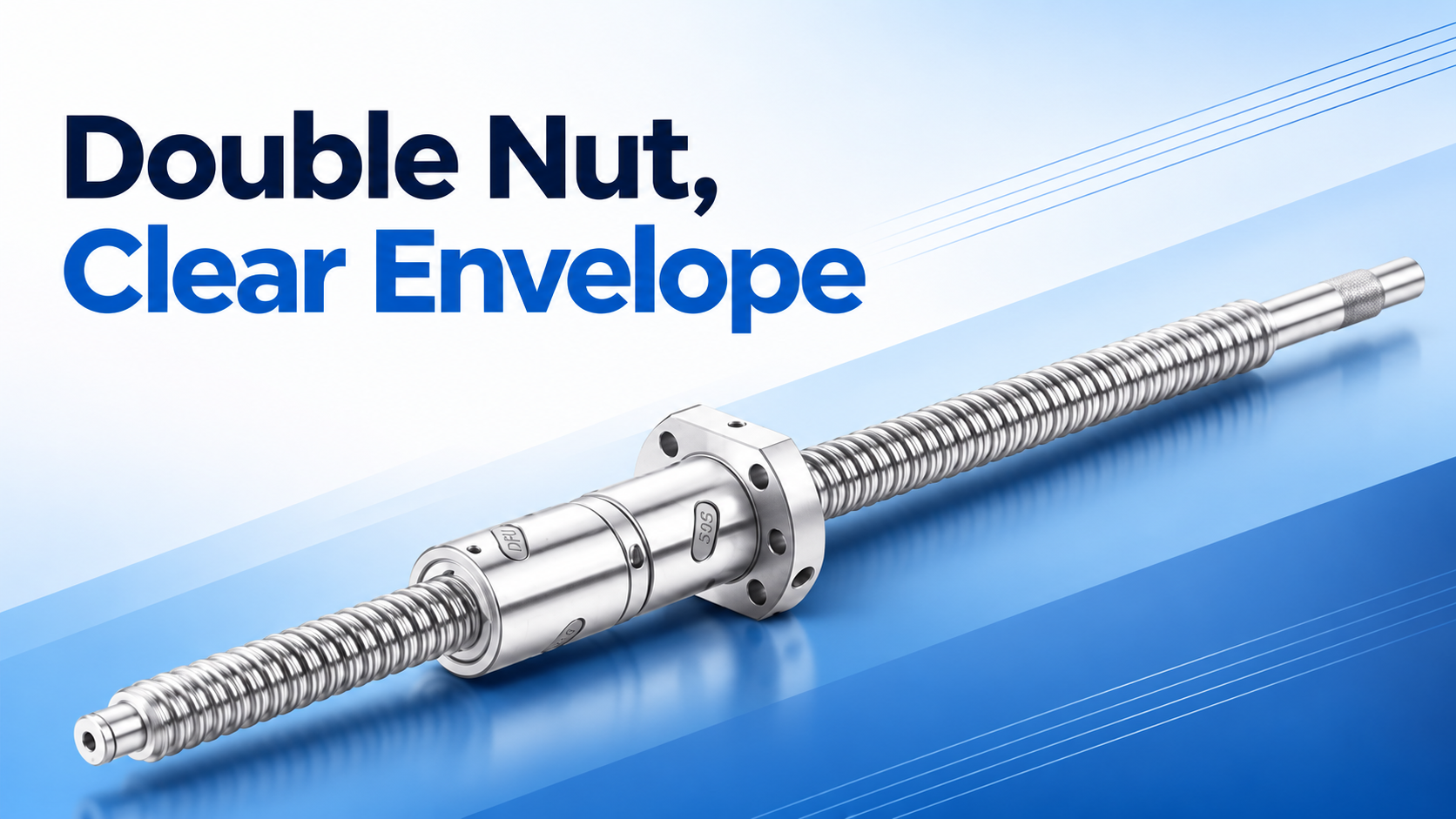
Wangong's DFU double-nut ball screw is an appropriate product reference for that review. The range drawing and model table describe dimensions that vary with the selected size. The letters DFU help identify a family, but they do not replace the dimensional drawing of the actual screw-and-nut assembly being ordered.
Reserve space in the model before optimizing travel
Begin with a simplified solid representing the complete nut envelope. Include the flange, mounting hardware and features that the supplier identifies as part of the assembly. Use the approved dimensions rather than an outline scaled from a catalogue photograph. A long nut can consume travel at one end of an axis even when the screw shaft itself fits comfortably.
Move that envelope through the intended stroke in the machine model. Check both travel extremes and any service position. Guards, bearing supports, brackets and cable routing can occupy space that appears empty in an isolated component drawing. The useful question is whether the installed assembly can move and be serviced, not merely whether it can be inserted during initial construction.
Read the model row with its drawing
The DFU double-nut ball screw has size-specific dimensions in its product information. Confirm which symbols refer to the nut body, flange and mounting pattern. Dimensions such as overall nut length should not be confused with usable screw travel or total shaft length.
| Design interface | Information to confirm | Layout consequence |
|---|---|---|
| Nut envelope | Complete length and maximum profile | Available stroke and adjacent clearance |
| Flange | Diameter, thickness and hole pattern | Carriage connection and tool access |
| Lubrication point | Position and connection detail | Service route through the machine |
| Screw ends | Approved end-machining drawing | Bearing and drive interfaces |
Keep the selected model designation and drawing revision together. If the supplier proposes another size or construction, repeat the envelope check. Similar lead and diameter do not guarantee equal flange geometry, assembly length or mounting access.
Preload is a selection decision, not a free benefit
Double-nut arrangements can be used to establish preload and control axial clearance, but the appropriate preload depends on the application. It affects behavior such as stiffness, friction and heating. A purchasing brief should not simply request the highest available preload because the axis needs accurate movement.
Provide the duty, loading, speed and accuracy requirements to the supplier. Ask for the proposed assembly specification and its applicable limits. Avoid translating a general product description into a guarantee of zero positioning error for the complete machine. Bearings, couplings, structure, control and thermal behavior also influence axis performance.
Do not adjust or separate the nut assembly casually during incoming inspection. Follow the manufacturer's handling instructions. Removing a nut from its screw without the correct procedure can disturb the ball circuit or the matched assembly. A sample review should preserve the supplied configuration unless a qualified procedure explicitly calls for disassembly.
Check installation access in reverse
It is easy to model the final position and forget how an installer reaches the fasteners. Work backwards from the assembled axis: can the mounting bolts be inserted and tightened with the intended tools? Can the lubrication connection be reached without removing an unrelated machine module? Can the assembly be replaced along the planned maintenance route?
- Place the approved nut envelope in the carriage model.
- Check the full motion and service positions.
- Review mounting-tool access and fastener insertion.
- Confirm the lubrication route and protection arrangement.
- Review installation and replacement access before releasing drawings.
That sequence can reveal a problem while it is still a bracket or carriage design issue. Discovering it after end machining and assembly can force more expensive changes to shaft length, travel or surrounding structures.
Keep the load calculation and space check connected
The envelope review does not establish load capacity or life. Those require the selected product data and the relevant application calculation. Conversely, a satisfactory load calculation does not prove that the assembly fits or can be installed. Both should refer to the same model and configuration.
If the axis design changes, revisit both. A longer stroke may change screw support conditions, while a carriage change can move the applied load or restrict the nut. The review should follow the final machine arrangement rather than preserve an approval that applied to an earlier layout.
The envelope model should include any supplier-specified features that project beyond the simplified cylindrical nut body. A lubrication fitting, flange bolt or mounting detail can become the first point of interference even when the nominal body clears. Identify which dimensions are fixed and which remain provisional during the design stage. If a placeholder model is used, mark it clearly and replace it with the approved geometry before release. Otherwise an early space estimate can survive unnoticed into machining drawings and become an expensive assumption in the finished carriage.
What to send with a DFU enquiry
Provide the selected nominal size and lead, shaft and end-machining drawing, carriage interface, required travel and service constraints. Add the operating information needed for preload and life selection. Mark unresolved dimensions clearly instead of allowing an estimated catalogue outline to become an approved production drawing.
A double-nut ball screw should enter the axis design as a complete assembly with a real envelope. Reserving that space early lets the designer use the intended product without discovering that the extra nut length has quietly consumed the travel or maintenance access the machine needed.
keep
in touch.
in touch.
-

Address: No.186 Xianglong Road, Lishui City, 323000 Zhejiang, China
-

E-Mail: lydia@wangong.net
-

Tel: +86-13666550158
Copyright © 2026 Lishui Wangong Precision Machinery Co., Ltd.

Ball Screw Manufacturer