 English
 Português
 русский
 Español
News ·
News ·
News ·
News ·
News ·
News ·
News ·
News ·
News ·
News ·
News ·
News ·
News ·
News ·
News ·
News ·

About us
Our team is proud to offer on time guarantee and product guarantee to customer satisfaction.
Read Morecontact info
- No.186 Xianglong Road, Lishui City, 323000 Zhejiang, China
- +86-13666550158
- lydia@wangong.net
Posted by Wangong
Ball Screw End Machining: Confirm the Bearing and Coupling Interfaces
A ball screw specification can identify the shaft diameter, lead and nut while leaving its machined ends undefined. Those ends connect the screw to the support bearings and drive, so they need their own controlled drawing. Ball screw end machining should be reviewed as an interface task, with the adjacent components and assembly arrangement available to the supplier.
For machine builders and replacement-parts buyers, the practical question is whether the supplied shaft will match the intended support and coupling. A familiar series name or overall length does not settle that fit. Clear drawings also prevent a quotation for a plain shaft from being compared with one that includes finished end machining.
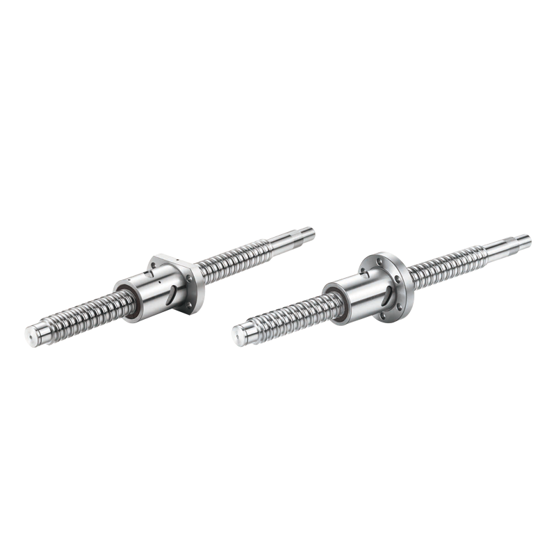
Interfaces to settle before machining
Identify the screw and support arrangement
Start with the complete screw reference, including diameter, lead, nut configuration and required travel. For an SFY series ball screw, as for another series, the product selection should be linked to the machine layout rather than treated as an end-machining specification by itself.
Show which end is driven and how each end is supported. Identify the actual support units, bearings or mounting arrangement proposed by the designer. A generic description such as standard support may be insufficient when more than one dimensional version is available.
For replacements, provide the existing drawing where possible and photographs showing the whole assembly. Measurements of a worn or damaged component should be reviewed carefully. They may help identify the arrangement, but they should not automatically become the manufacturing nominal dimensions.
Describe every ball screw bearing seat
The ball screw bearing seat must match the bearing arrangement defined by the machine designer. Record the relevant diameters, seat lengths, shoulder positions and associated retaining features on the end drawing. The supplier needs the intended interfaces, not only a cropped photograph of the shaft end.
Ask the designer to specify the required fits, surface requirements and geometric controls. These values depend on the actual design and adjacent components. A universal tolerance copied from another screw or support assembly can create an unintended requirement.
Review the shoulder and clearance details against the bearing and retaining components. A nominal diameter may be correct while the adjacent radius or axial arrangement prevents proper seating. Resolve these details through the controlled drawing before machining starts.
Confirm the ball screw coupling interface
The ball screw coupling interface should identify the selected coupling and the relevant shaft-end geometry. Confirm the required diameter, engagement length and any specified flat, keyway or other feature. Do not assume that every coupling requires the same shaft preparation.
Include the motor-side arrangement in the layout review so that the complete connection can be assessed. The coupling supplier's drawing and assembly requirements should inform the interface, while the machine designer remains responsible for the overall drive arrangement.
Keep fastening and assembly instructions separate from the machining drawing where appropriate, but ensure the documents agree. An accurately machined end cannot compensate for an incompatible coupling selection or an unreviewed assembly change.
Drawing release and inspection
Put the interface details into one drawing review
| Drawing item | Information to define | Interface affected |
|---|---|---|
| Overall shaft length | Reference ends and approved dimension | Machine envelope |
| Support-end geometry | Seats, shoulders and retaining features | Bearing arrangement |
| Drive-end geometry | Diameter, length and specified features | Coupling connection |
| Dimensional controls | Fits and tolerances set by the designer | Component compatibility |
| Geometric controls | Required relationships and datums | Assembly alignment |
| Drawing status | Part reference, units and revision | Manufacturing release |
A compact end-detail drawing can be useful, but it must remain connected to the whole shaft. Label the drive and support ends unambiguously. If the drawing contains multiple options, mark the ordered option rather than leaving the workshop to choose between similar views.
Distinguish useful travel from total length
The shaft's overall length, threaded region and available nut movement describe different aspects of the assembly. Keep them separately identified. Increasing an end-machined length without reviewing the complete layout can affect the space available for the intended travel.
Provide the required operating envelope and any end-clearance requirements for engineering review. Do not use the nut touching a physical end as an assumed travel limit. The machine's permitted movement and protection arrangements belong in the complete design assessment.
If the supplier proposes a drawing change, ask how it affects the adjacent support, coupling and nut positions. A revision that appears minor on one end detail may alter another component's location. Keep the agreed response with the drawing rather than relying on a verbal explanation.
Agree inspection before the order is released
Ask which dimensions and features will be checked, how the results will be recorded and whether a dimensional report is included in the quotation. The inspection scope should reflect the approved drawing and the buyer's receiving requirements.
Separate end-machining inspection from ball screw travel accuracy, preload or load-rating claims. These are different characteristics with different acceptance bases. A report confirming one feature does not automatically demonstrate every performance requirement of the assembled axis.
For incoming inspection, retain the matching support and coupling references. Do not force components together to overcome an unexpected fit. Record the measured discrepancy and seek a drawing-based resolution before modifying the supplied shaft or adjacent parts.
Repeat-order identification
Make repeat orders traceable
Store the final drawing revision with the screw part number and purchase order. If the support or coupling changes, review the end machining again even when the screw diameter and lead remain unchanged. Old drawings should be clearly distinguished from the released version.
Spare-part orders should reference that same record. A request for the same ball screw as last time can be ambiguous when a machine builder has several axis configurations. Include the controlled part reference and end-machining drawing to identify the intended assembly.
Send a complete machining enquiry
- Identify the full screw and nut configuration.
- Show the driven end and support arrangement.
- Attach the bearing and coupling interface drawings.
- Define fits and geometric requirements through the designer.
- Clarify whether end machining and inspection are included.
- Release one approved revision for production and repeat orders.
A coordinated interface drawing gives the supplier a clear manufacturing basis and the buyer a practical inspection reference. Resolve the support and drive details before comparing quotations so the finished ball screw can be assessed against the assembly it is intended to serve.
keep
in touch.
in touch.
-

Address: No.186 Xianglong Road, Lishui City, 323000 Zhejiang, China
-

E-Mail: lydia@wangong.net
-

Tel: +86-13666550158
Copyright © 2026 Lishui Wangong Precision Machinery Co., Ltd.

Ball Screw Manufacturer